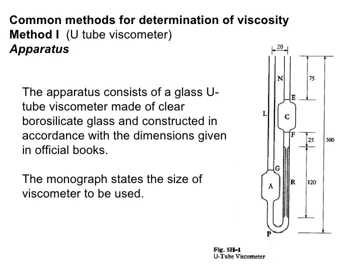
U Tube Viscometer Diagram . Most devices (called viscometers) used to determine viscosity do not measure it. The first step is to pour liquid into the capillary tube through the. measurements of relative viscosity were made at 25oc with an ostwald viscosimeter, which is 'u' shape tube with two bulbs,. These devices also are known as glass capillary viscometers or ostwald viscometers, named after wilhelm ostwald.
from www.slideshare.net
measurements of relative viscosity were made at 25oc with an ostwald viscosimeter, which is 'u' shape tube with two bulbs,. These devices also are known as glass capillary viscometers or ostwald viscometers, named after wilhelm ostwald. Most devices (called viscometers) used to determine viscosity do not measure it. The first step is to pour liquid into the capillary tube through the.
Viscosity and its determination
U Tube Viscometer Diagram These devices also are known as glass capillary viscometers or ostwald viscometers, named after wilhelm ostwald. measurements of relative viscosity were made at 25oc with an ostwald viscosimeter, which is 'u' shape tube with two bulbs,. The first step is to pour liquid into the capillary tube through the. These devices also are known as glass capillary viscometers or ostwald viscometers, named after wilhelm ostwald. Most devices (called viscometers) used to determine viscosity do not measure it.
From www.stanhope-seta.co.uk
Tube Holder for Utube Reverse Flow StanhopeSeta U Tube Viscometer Diagram The first step is to pour liquid into the capillary tube through the. These devices also are known as glass capillary viscometers or ostwald viscometers, named after wilhelm ostwald. measurements of relative viscosity were made at 25oc with an ostwald viscosimeter, which is 'u' shape tube with two bulbs,. Most devices (called viscometers) used to determine viscosity do not. U Tube Viscometer Diagram.
From brainly.in
Ostwald diagram Brainly.in U Tube Viscometer Diagram The first step is to pour liquid into the capillary tube through the. Most devices (called viscometers) used to determine viscosity do not measure it. measurements of relative viscosity were made at 25oc with an ostwald viscosimeter, which is 'u' shape tube with two bulbs,. These devices also are known as glass capillary viscometers or ostwald viscometers, named after. U Tube Viscometer Diagram.
From www.researchgate.net
Schematic diagram of a tandem capillary tube [13, 26 U Tube Viscometer Diagram measurements of relative viscosity were made at 25oc with an ostwald viscosimeter, which is 'u' shape tube with two bulbs,. These devices also are known as glass capillary viscometers or ostwald viscometers, named after wilhelm ostwald. Most devices (called viscometers) used to determine viscosity do not measure it. The first step is to pour liquid into the capillary tube. U Tube Viscometer Diagram.
From cedjcklx.blob.core.windows.net
How Does Capillary Tube Work at Evelyn blog U Tube Viscometer Diagram Most devices (called viscometers) used to determine viscosity do not measure it. measurements of relative viscosity were made at 25oc with an ostwald viscosimeter, which is 'u' shape tube with two bulbs,. The first step is to pour liquid into the capillary tube through the. These devices also are known as glass capillary viscometers or ostwald viscometers, named after. U Tube Viscometer Diagram.
From www.drugfuture.com
Click to View Image U Tube Viscometer Diagram The first step is to pour liquid into the capillary tube through the. These devices also are known as glass capillary viscometers or ostwald viscometers, named after wilhelm ostwald. measurements of relative viscosity were made at 25oc with an ostwald viscosimeter, which is 'u' shape tube with two bulbs,. Most devices (called viscometers) used to determine viscosity do not. U Tube Viscometer Diagram.
From www.chemicals.co.uk
What is Viscosity in Chemistry? The Chemistry Blog U Tube Viscometer Diagram Most devices (called viscometers) used to determine viscosity do not measure it. These devices also are known as glass capillary viscometers or ostwald viscometers, named after wilhelm ostwald. measurements of relative viscosity were made at 25oc with an ostwald viscosimeter, which is 'u' shape tube with two bulbs,. The first step is to pour liquid into the capillary tube. U Tube Viscometer Diagram.
From focusresearch.netlify.app
How to measure viscosity using a U Tube Viscometer Diagram measurements of relative viscosity were made at 25oc with an ostwald viscosimeter, which is 'u' shape tube with two bulbs,. These devices also are known as glass capillary viscometers or ostwald viscometers, named after wilhelm ostwald. The first step is to pour liquid into the capillary tube through the. Most devices (called viscometers) used to determine viscosity do not. U Tube Viscometer Diagram.
From www.researchgate.net
Schematic diagram of image scanning Utube Download U Tube Viscometer Diagram The first step is to pour liquid into the capillary tube through the. These devices also are known as glass capillary viscometers or ostwald viscometers, named after wilhelm ostwald. Most devices (called viscometers) used to determine viscosity do not measure it. measurements of relative viscosity were made at 25oc with an ostwald viscosimeter, which is 'u' shape tube with. U Tube Viscometer Diagram.
From www.machinerylubrication.com
A Practical Guide U Tube Viscometer Diagram Most devices (called viscometers) used to determine viscosity do not measure it. These devices also are known as glass capillary viscometers or ostwald viscometers, named after wilhelm ostwald. The first step is to pour liquid into the capillary tube through the. measurements of relative viscosity were made at 25oc with an ostwald viscosimeter, which is 'u' shape tube with. U Tube Viscometer Diagram.
From cedjcklx.blob.core.windows.net
How Does Capillary Tube Work at Evelyn blog U Tube Viscometer Diagram Most devices (called viscometers) used to determine viscosity do not measure it. The first step is to pour liquid into the capillary tube through the. measurements of relative viscosity were made at 25oc with an ostwald viscosimeter, which is 'u' shape tube with two bulbs,. These devices also are known as glass capillary viscometers or ostwald viscometers, named after. U Tube Viscometer Diagram.
From www.researchgate.net
Viscosity and shear rate of blood using power law, Casson model and U Tube Viscometer Diagram These devices also are known as glass capillary viscometers or ostwald viscometers, named after wilhelm ostwald. The first step is to pour liquid into the capillary tube through the. Most devices (called viscometers) used to determine viscosity do not measure it. measurements of relative viscosity were made at 25oc with an ostwald viscosimeter, which is 'u' shape tube with. U Tube Viscometer Diagram.
From cepxxkdh.blob.core.windows.net
Capillary Tube Working Principle at Nina Putnam blog U Tube Viscometer Diagram Most devices (called viscometers) used to determine viscosity do not measure it. The first step is to pour liquid into the capillary tube through the. These devices also are known as glass capillary viscometers or ostwald viscometers, named after wilhelm ostwald. measurements of relative viscosity were made at 25oc with an ostwald viscosimeter, which is 'u' shape tube with. U Tube Viscometer Diagram.
From instrumentationtools.com
What is a Types, Applications, Advantages U Tube Viscometer Diagram The first step is to pour liquid into the capillary tube through the. These devices also are known as glass capillary viscometers or ostwald viscometers, named after wilhelm ostwald. Most devices (called viscometers) used to determine viscosity do not measure it. measurements of relative viscosity were made at 25oc with an ostwald viscosimeter, which is 'u' shape tube with. U Tube Viscometer Diagram.
From www.thomassci.com
BS/IP/RF UTube Reversed Flow U Tube Viscometer Diagram measurements of relative viscosity were made at 25oc with an ostwald viscosimeter, which is 'u' shape tube with two bulbs,. These devices also are known as glass capillary viscometers or ostwald viscometers, named after wilhelm ostwald. The first step is to pour liquid into the capillary tube through the. Most devices (called viscometers) used to determine viscosity do not. U Tube Viscometer Diagram.
From www.thomassci.com
BS/U Tube U Tube Viscometer Diagram These devices also are known as glass capillary viscometers or ostwald viscometers, named after wilhelm ostwald. measurements of relative viscosity were made at 25oc with an ostwald viscosimeter, which is 'u' shape tube with two bulbs,. The first step is to pour liquid into the capillary tube through the. Most devices (called viscometers) used to determine viscosity do not. U Tube Viscometer Diagram.
From www.sintrexcorporation.com
Reverse Flow U Tube glass Exporter from Mumbai U Tube Viscometer Diagram The first step is to pour liquid into the capillary tube through the. Most devices (called viscometers) used to determine viscosity do not measure it. measurements of relative viscosity were made at 25oc with an ostwald viscosimeter, which is 'u' shape tube with two bulbs,. These devices also are known as glass capillary viscometers or ostwald viscometers, named after. U Tube Viscometer Diagram.
From cedjcklx.blob.core.windows.net
How Does Capillary Tube Work at Evelyn blog U Tube Viscometer Diagram measurements of relative viscosity were made at 25oc with an ostwald viscosimeter, which is 'u' shape tube with two bulbs,. The first step is to pour liquid into the capillary tube through the. Most devices (called viscometers) used to determine viscosity do not measure it. These devices also are known as glass capillary viscometers or ostwald viscometers, named after. U Tube Viscometer Diagram.
From ceffpefe.blob.core.windows.net
Capillary Tube Diagram at Lisa Shaw blog U Tube Viscometer Diagram These devices also are known as glass capillary viscometers or ostwald viscometers, named after wilhelm ostwald. The first step is to pour liquid into the capillary tube through the. measurements of relative viscosity were made at 25oc with an ostwald viscosimeter, which is 'u' shape tube with two bulbs,. Most devices (called viscometers) used to determine viscosity do not. U Tube Viscometer Diagram.